
The promise of home energy independence in Australia is highly attractive. Generating your own power via rooftop solar, storing it for the night using a home battery, and using it to power a vehicle via a dedicated EV Charger feels like the ultimate escape from soaring retail electricity tariffs. However, many Australian homeowners rush into these investments only to be blindsided by massive, unexpected installation costs before a single piece of hardware is even unboxed.
If your home infrastructure is not prepared, what looked like a straightforward upgrade can turn into an expensive asset integration challenge. At Top Electricians, we see households face these hidden bottlenecks regularly. Transitioning your property into a mini power plant requires moving beyond standard component brochures and conducting a thorough technical property audit.
The Compliance Trap: Why Modern Clean Energy Tech Fails on Legacy Australian Switchboards
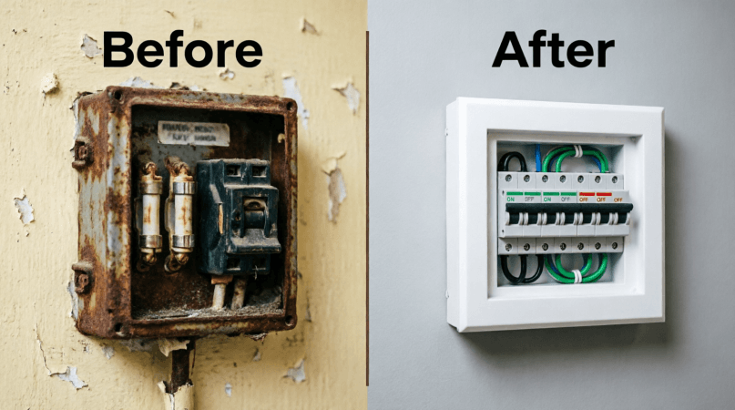
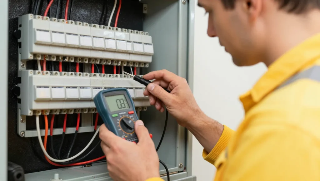
Many homeowners believe that purchasing Clean Energy Council approved hardware is the only requirement for an installation. In reality, your existing main switchboard acts as the absolute gatekeeper for your entire system. If you live in an established Australian suburb with a home built between the 1960s and the late 1990s, your electrical panel likely relies on an old Ceramic Fuse Rewireable Carrier system.
Under the strict mandates of the AS/NZS 3000 wiring rules, a licensed electrical contractor cannot legally connect a solar generation array, a battery system, or a high-draw vehicle charger to an un-upgraded switchboard containing these legacy components. The moment a new energy asset alters the electrical footprint of the property, the entire panel must be brought up to modern regulatory standards.
Mandatory Compliance Alert: Upgrading a legacy switchboard means completely removing retrofitted ceramic carriers and replacing them with modern RCBO Safety Switches (Residual Current Breakers with Overcurrent protection). If your older switchboard backing panel contains hazardous materials like asbestos, specialized removal and containment protocols are legally enforced. This compliance correction adds an immediate, non-negotiable structural cost of $3,000 to $4,500 to your project before any solar or charging equipment can be mounted.
Decoding the Post-May 2026 STC Battery Rebate Taper Framework
Navigating the financial incentives for energy storage requires an understanding of recent legislative updates. The Federal Government expanded the Small-scale Renewable Energy Scheme via the Cheaper Home Batteries Program, which significantly reduces upfront costs. However, a major structural adjustment implemented by the Clean Energy Regulator (CER) altered the financial calculation for sizing home storage systems.
The program creates and trades Small-scale Technology Certificates (STCs) to provide an upfront point-of-sale discount. The incentive model applies a strict sliding-scale taper based on the total storage capacity of the installation. Sizing your system past a single storage block without reviewing these tiers can drastically reduce your financial returns.
| Battery System Total Usable Capacity | CER STC Rebate Funding Tier | Effective Financial Discount per kWh |
| 0 kWh up to 14 kWh (Inclusive) | 100% of the active STC factor applied | Maximum Upfront Point-of-Sale Discount (~$372/kWh) |
| Greater than 14 kWh up to 28 kWh | Tapered to 60% of the active STC factor | Diminishing Rebate Value on Supplementary Modules |
| Greater than 28 kWh up to 50 kWh | Collapsed to 15% of the active STC factor | Minimal Subsidy; Full Retail Pricing Applies |
This tiered framework aims to prevent homeowners from over-sizing systems purely to maximize government subsidies. Sizing your storage to sit precisely within the 13.5 kWh to 14 kWh window captures the maximum relative discount. It is also important to note that the Usable Capacity Cushion determines the final certificate generation value based on the actual installation date, rather than the date you sign the sales contract.
The Physical Property Audit: Connectivity, Cages, and Future-Proofing
Even if your switchboard passes modern compliance checks, physical and architectural layout barriers can still disrupt an installation. Modern clean energy systems are highly reliant on stable data communications to function correctly.
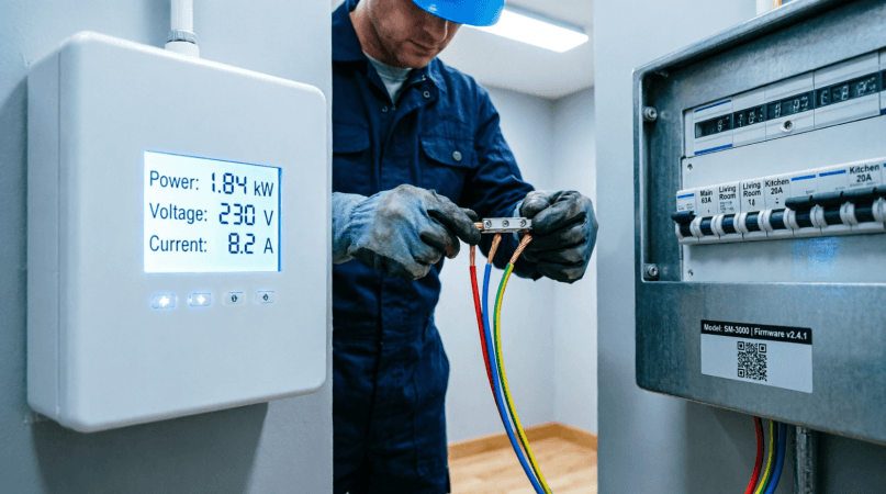
- The Switchboard Faraday Cage: Modern hybrid inverters and vehicle charging units require consistent data communication to read local grid signals and report performance metrics. Housing smart meters and communication modules inside a heavy sheet-metal enclosure box often creates a Faraday Enclosure Interference zone, completely blocking 4G or local Wi-Fi signals. If a signal cannot penetrate the metal enclosure, your system will fail to process real-time optimization commands.
- Dynamic Export Limitations: Network operators across Australia, including state-level Distributed Network Service Provider (DNSP) entities, increasingly mandate the use of Dynamic Operating Envelopes (DOEs). These protocols allow the grid utilities to remotely manage or throttle your solar export limits down to zero during peak solar generation days to maintain localized grid stability. If your site lacks a robust internet connection to receive these automated utility signals, your grid connection application may be rejected entirely.
- Garage and Wall Cavity Clearances: Upgrading your property for an electric vehicle charger involves analyzing physical cable runs. Homeowners often assume a charger can easily be placed on any garage wall. However, if the garage does not share an accessible internal wall cavity with the main outdoor meter box, installation paths become complex. Future-proofing your home requires checking for a clear pathway or pre-installing a dedicated V2G Pre-wiring Conduit (minimum 25mm diameter) to support future bi-directional vehicle-to-grid power flows without requiring invasive external brick trenching later on.
Beyond Hardware: The 24-Hour Behavioral Load and 63A Single-Phase Calculations
The most significant mistake made during basic solar and vehicle charging site assessments is focusing entirely on hardware capacity while ignoring household consumption patterns. Most standard residential properties across Australia operate on a standard 63-Amp single-phase power supply grid connection. This 63A threshold represents the absolute limit of electrical current your home can draw from the street network before the main service fuse fails.
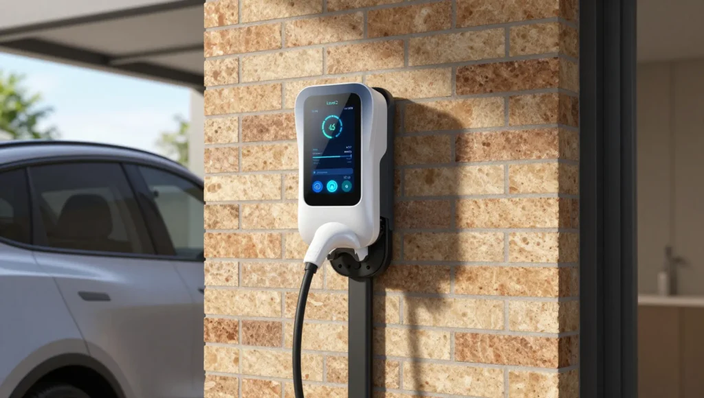
Adding a modern Level 2 fast vehicle charger introduces a heavy electrical load to your domestic infrastructure. A standard single-phase vehicle charger draws a continuous 32 Amps of current to deliver a 7kW charging rate, immediately consuming over half of your property’s entire electrical capacity.
The 63A Maximum Demand Peak Breakdown
To understand how easily a standard single-phase service connection can become overloaded, consider this realistic evening scenario. The household returns home at 6:30 PM during peak time-of-use tariff rates:
- Level 2 Fast Charger (Active): Draws 32 Amps (7kW continuous draw)
- Multi-Zone Induction Cooktop (Active for Dinner): Draws 20 Amps
- Split-System Climate Control (Running Unit): Draws 15 Amps
- Background Household Loads (Fridge, Lighting, Entertainment): Draws 5 Amps
- Total Concurrent Electrical Demand: 72 Amps
In this scenario, the total demand reaches 72 Amps, which quickly exceeds the 63A main street service fuse capacity and causes a total household power failure. This is why a detailed Maximum Demand Calculation is a vital part of your planning phase.
To solve this issue without paying $10,000 or more for a physical utility infrastructure upgrade to three-phase power, you must utilize intelligent energy management devices. Ensuring your system includes CT Metering Clamps installed directly at the main grid connection point allows your vehicle charger to monitor real-time household power draw. When you turn on high-draw appliances like a cooktop, the intelligent system automatically down-throttles the vehicle charging speed from 7kW down to 3.7kW (16 Amps), safely balancing your electrical load below the single-phase fuse limit.
The Controlled Load 2 Relay Trap: Isolating Battery Circuits Natively
When adding a battery backup to a home with an existing electric hot water tank or slab heating system, you encounter the nuance of Controlled Load 2 Tariff Rippling configurations. In Australia, networks offer dedicated, cheaper off-peak metering circuits commonly labeled Controlled Load 1 or Controlled Load 2 controlled by a physical ripple relay switch in your meter box. This relay automatically triggers when the utility network broadcasts a high-frequency audio frequency ripple signal down the line to turn on heavy heating elements during low-demand periods.
If your installing electrician does not audit the building’s wiring distribution prior to mounting a modern storage battery, a critical integration failure often occurs:
If the storage system’s central energy management gateway is wired upstream of the entire switchboard without isolating these specialized secondary consumer mains, the battery interprets the sudden midnight activation of a 3.6kW hot water heating element as a general household load spike. The battery will immediately try to power this demand, completely emptying its Usable Capacity Cushion into a hot water tank in less than three hours. By the time morning peak utility pricing starts, your home storage asset is completely empty.
Preventing this issue requires a physical pre-installation check. Your contractor must inspect your switchboard’s wiring layout and physically separate the ripple relay contactor busbars from the battery’s active backup gateway. This ensures your home water heating remains powered directly by the cheap off-peak grid network, keeping your stored battery power reserved for your standard morning household loads.
Mastering Your Pre-Installation Strategy
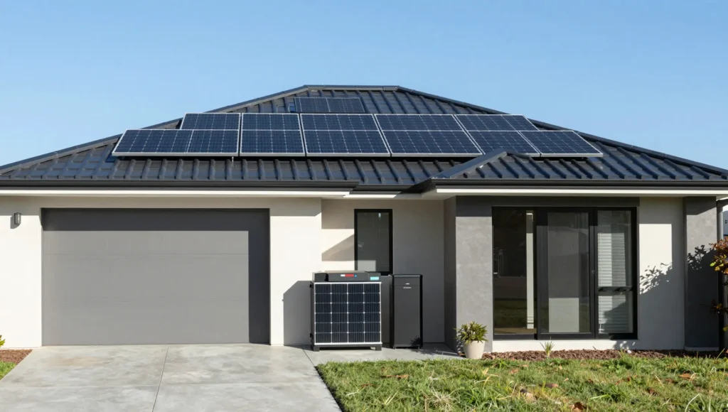
Transforming an Australian residential property into an integrated generation and storage system requires careful planning. Moving forward without checking structural compatibility, local distribution regulations, and physical connectivity constraints increases your risk of project delays and unexpected costs. Before signing an installation contract or paying a deposit for clean energy hardware, ensure your installation plan accounts for the following technical checkpoints:
- Confirm your main switchboard contains modern circuit breakers and is free from asbestos backing panels or older ceramic fuse carriers to avoid mandatory upgrade costs under AS/NZS 3000 rules.
- Check that your combined continuous energy consumption matches the 63A single-phase network service fuse threshold using a detailed Property Load Profiling assessment.
- Verify your selected charging hardware includes real-time CT Metering Clamps to dynamically throttle vehicle power draw during periods of high household demand.
- Size your chemical storage block to match the post-May 2026 sliding-scale incentive tiers regulated by the Clean Energy Regulator (CER) to maximize your point-of-sale discount.
- Test for cellular and wireless signal strength directly inside your metal meter box enclosure to ensure your smart infrastructure can communicate with the grid.
- Inspect the path between your garage wall and main meter panel for an open cavity or a pre-installed 25mm conduit path to support future bi-directional power configurations.
- Verify with your installer that all dedicated heating circuits are isolated from your battery storage systems to prevent accidental battery drainage during off-peak ripple relay activation cycles.
Final Thoughts: Designing a Future-Ready Energy Ecosystem
Upgrading a property with solar panels, battery storage, or EV charging infrastructure is not simply a product selection decision but a comprehensive electrical system upgrade. It involves evaluating supply capacity, switchboard condition, wiring integrity, load demands, and compliance requirements to ensure the installation performs safely and reliably over time. A thorough pre-installation assessment identifies limitations early, clarifies upgrade requirements, and aligns system design with current usage and future demand.
This approach minimizes the risk of overloads, compliance issues, and unexpected costs while supporting long-term performance and safety. Careful planning, accurate technical evaluation, and adherence to standards remain the foundation of a successful and future-ready electrical upgrade.
By addressing infrastructure gatekeepers like switchboard compliance, peak maximum demand calculations, and specialized tariff routing before hardware is bolted to the wall, you insulate your investment from common installation failures. If you are ready to baseline your property’s true electrical capacity and protect your clean energy investment from hidden installation roadblocks, contact the specialized team at Top Electricians today to schedule your comprehensive, code-compliant property readiness audit.
Technical Clean Energy Integration FAQ
Can I install a 7kW (32A) EV charger on a standard single-phase home switchboard?
Yes, you can install a 7kW EV Charger on a single-phase supply, but it requires careful load management. Because a 32A charger consumes over half of a standard 63A main service fuse capacity, it should be paired with intelligent energy controllers. These systems use current monitoring clamps to dynamically reduce vehicle charging speeds when other heavy appliances are running, preventing your main building breaker from overloading.
What is the difference between Type A and Type B RCDs for vehicle charging infrastructure?
Type A and Type B Residual Current Devices (RCDs) handle different types of electrical fault currents. Standard Type A safety switches protect against standard alternating current (AC) and pulsating direct current (DC) leaks. However, modern electric vehicle charging systems can introduce smooth, continuous DC fault currents into your home’s electrical system. A Type B RCD is specifically engineered to detect these smooth DC leaks above 6mA and safely isolate the circuit, preventing dangerous blind spots on standard household safety switches.
Why does my hybrid solar inverter require a continuous internet connection to maintain compliance?
Under the current AS/NZS 4777.2:2020 utility connection standards, all new grid-interactive inverters installed throughout Australia must support remote communication capabilities. This allows your regional distribution network utility to use automated management systems to dynamically adjust or limit your solar export capacity during periods of high grid stress. If your equipment loses its internet connection, it cannot receive these mandatory balancing signals, which can lead to your system being disconnected from the grid or having its export permissions restricted.
Will a home storage battery automatically power my hot water system during a power outage?
By default, home storage batteries should not power heavy heating elements during a utility power outage. Electric storage hot water systems typically draw between 3.6kW and 4.8kW of continuous power, which can easily overwhelm a residential backup inverter. During an installation, these heavy heating loads should be wired into separate, non-backed-up circuits to ensure your stored battery capacity is reserved for critical devices like refrigeration, medical equipment, lighting, and communication infrastructure.
How do the updated 2026 STC rebate tiers impact the upfront cost of multi-battery installations?
The updated framework reduces the financial incentives for larger residential battery installations. While single modules up to 14 kWh receive the maximum point-of-sale discount, any additional capacity between 14 kWh and 28 kWh has its funding reduced to a 60% incentive rate. Sizing an installation beyond 28 kWh drops the certificate value to 15%. This creates a sharp drop-off in financial returns for larger residential systems, making single-module configurations the optimal choice for cost efficiency.